Interfacial Engineering in Structural Battery Composites
A Review of Electrolyte-Matrix Compatibility and Mechanical Robustness
Introduction
The pursuit of lighter, more efficient vehicles and aircraft has led engineers to a fascinating question: What if the structure itself could store energy?
Structural battery composites represent a paradigm shift in multifunctional materials—combining load-bearing capability with electrochemical energy storage within a single material system. Rather than treating batteries and structures as separate subsystems competing for mass and volume, this technology integrates them at the material level.
💡 KEY INSIGHT
If structural mass can also store energy, the effective specific energy of the system increases dramatically—even if the material's intrinsic energy density is modest compared to conventional batteries.
This comprehensive review examines 86 peer-reviewed publications spanning 2010-2025 to synthesize current understanding of interfacial engineering challenges in structural battery composites. We focus specifically on the interfaces—between electrolyte and structural matrix, between electrode and electrolyte, and between fiber and matrix—because these interfaces ultimately determine whether a structural battery succeeds or fails.
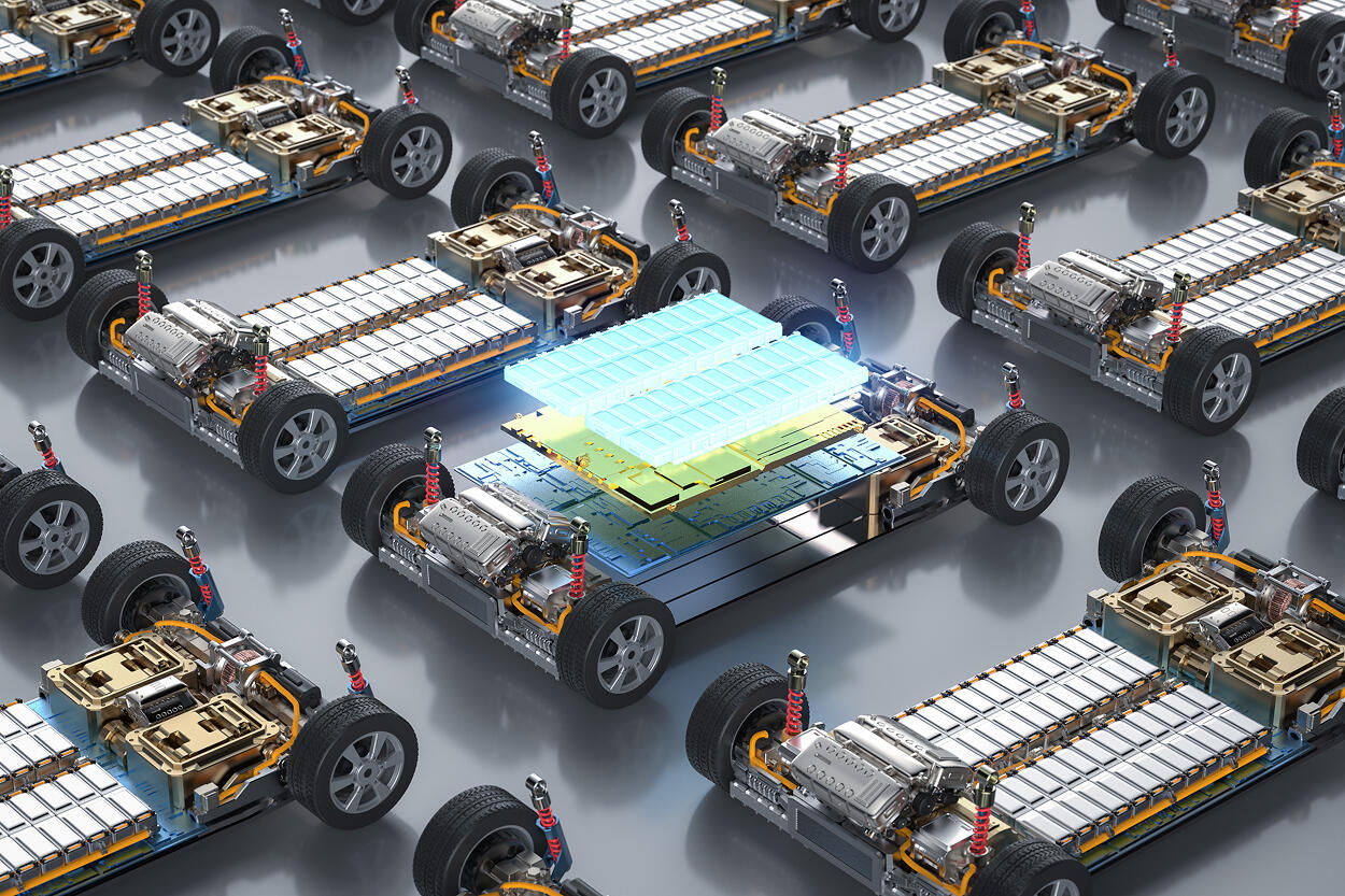
Structural Battery Composite Concept
Multifunctional laminate architecture — simultaneous energy storage & structural load bearing
Why Structural Batteries Matter
The Mass Efficiency Argument
Consider a conventional electric vehicle: the battery pack and the vehicle structure are completely separate systems. The battery adds mass that contributes nothing to structural integrity, while the structure adds mass that stores no energy.
Traditional Approach
Structural Battery Approach
The math becomes compelling when you consider the multifunctional efficiency equation:
ηmf = Estored/Ebattery,ref + σmechanical/σstructure,ref
A material achieving just 20% of conventional battery energy density while providing 50% of structural performance delivers significant system-level benefits that pure energy density comparisons miss.
Current State-of-the-Art Performance
| Metric | Structural Battery | Conventional Li-ion | Ratio |
|---|---|---|---|
| Energy density | 24-37 Wh/kg | 250-300 Wh/kg | ~10-15% |
| Elastic modulus | 25-30 GPa | N/A | Structural function |
| Power density | 10-30 W/kg | 500-3000 W/kg | ~3-5% |
| Cycle life | 100-500 cycles | 500-2000 cycles | ~20-50% |
While absolute electrochemical values lag conventional batteries, the multifunctional benefit can offset this for mass-critical applications [1, 2].
The Core Architecture
Structural Battery Laminate Architecture
Exploded cross-section view — each layer serves simultaneous electrochemical and mechanical functions
The Components
A structural battery composite consists of three essential elements:
Carbon Fiber Electrodes
Anode: Carbon fibers that intercalate lithium ions. Cathode: Carbon fibers coated with active material (typically LiFePO₄). Dual function: electrical conductivity + mechanical reinforcement.
Structural Electrolyte
Ion-conducting polymer matrix (typically PEO-based). Structural resin component (epoxy or bismalemide). Must achieve: ionic conductivity (~10⁻⁴ S/cm) + mechanical stiffness (~2-5 GPa).
Separator
Glass fiber fabric for electrical isolation. Maintains structural continuity. Contributes to mechanical properties.
The Architecture Challenge
The genius—and difficulty—of structural batteries lies in making these components work together: Electrochemically (conduct Li⁺ ions), Mechanically (transfer loads), and Simultaneously (without degrading each other).
This dual functionality creates unique interfacial challenges that don't exist in conventional batteries or structural composites.
Carbon Fiber as Structural Electrode
Bicontinuous Structural Electrolyte
Phase-separated polymer network — two interpenetrating continuous phases providing simultaneous ion conduction and mechanical stiffness
Why Carbon Fiber?
Carbon fiber serves as the structural electrode in most current designs because it uniquely combines:
It also features electrochemical activity (can intercalate lithium ions between graphene layers), chemical stability (resistant to electrolyte degradation), and manufacturing compatibility (existing composite processing infrastructure). However, this dual functionality requires careful optimization [6, 7].
Carbon Fiber Lithiation: The Anode
Carbon Fiber Lithiation Mechanism
Lithium-ion intercalation between graphene planes of PAN-based carbon fibers — the electrochemical basis for structural battery anodes
When carbon fiber acts as the anode, it intercalates lithium between graphene layers during charging:
C₆ + Li⁺ + e⁻ ⇌ LiC₆
Why the Gap?
Structural Disorder: PAN-based carbon fibers have turbostratic (disordered) graphene stacking, unlike the highly ordered structure in battery-grade graphite. This limits lithium access to intercalation sites [6].
Sizing Interference: Commercial carbon fibers have epoxy-compatible sizing that improves fiber-matrix adhesion but blocks lithium ion access. Removing sizing improves capacity but weakens the fiber-matrix interface [7].
Surface Oxide Groups: These create irreversible capacity loss in the first cycle through solid-electrolyte interphase (SEI) formation, consuming lithium permanently [8].
The Sizing Dilemma
Studies by Kjell et al. [6] demonstrated a clear trade-off:
| Treatment | Capacity (mAh/g) | Fiber-Matrix Adhesion | Mechanical Performance |
|---|---|---|---|
| As-received | 45 | Excellent | Baseline |
| Desized (solvent) | 125 | Poor | -40% strength |
| Electrochemical treatment | 95 | Good | -15% strength |
The electrochemical surface treatment route—which selectively removes sizing while minimizing fiber damage—has emerged as the most promising compromise.
Carbon Fiber as Cathode Substrate
For the cathode, carbon fiber serves as a current collector coated with active material, typically lithium iron phosphate (LiFePO₄):
Why LiFePO₄?
- Excellent structural stability during cycling (minimal lattice changes)
- High mechanical robustness
- Safe chemistry (no oxygen release during overcharge)
- Moderate voltage plateau (~3.4V vs Li/Li⁺)
Coating Challenges
Achieving uniform, well-adhered cathode coatings on carbon fiber presents significant challenges:
Coating Method: Electrophoretic deposition (EPD) has shown the most promise, creating uniform coatings even in fiber bundles [36].
Loading vs. Conductivity: Higher active material loading improves capacity but increases electrical resistance through the cathode layer.
Adhesion Durability: The cathode coating must survive composite manufacturing (often >100°C, mechanical pressure) and cycling-induced volume changes.
Recent work by Hagberg et al. [36] achieved:
Interface Evolution
During cycling, the carbon fiber/cathode interface develops a complex multi-layer structure:
Coated Carbon Fiber Cathode — Cross-Section Architecture
Radial layer structure from the carbon fiber core outward to the structural electrolyte, showing each functional interface
Structural Electrolyte Development
The structural electrolyte is arguably the most critical—and most challenging—component in structural battery design. It must simultaneously:
- Conduct lithium ions (electrochemical function)
- Transfer mechanical loads (structural function)
- Maintain both functions over hundreds of cycles
This dual requirement creates a fundamental property conflict.
The Conductivity-Stiffness Dilemma
Structural Electrolyte Property Space
Mapping the trade-off between ionic conductivity and elastic modulus — the central design challenge for multifunctional electrolytes
High Ionic Conductivity Requires:
- Polymer chain mobility (low Tg)
- High salt concentration
- Low crosslink density
- Amorphous phase dominance
High Mechanical Stiffness Requires:
- Restricted chain mobility (high Tg)
- High crosslink density
- Crystalline or glassy phases
- Strong intermolecular interactions
These requirements are largely contradictory [3, 10].
Structural Electrolyte Architectures
Researchers have developed several approaches to navigate this trade-off:
1. PEO/Epoxy Blends
Concept: Physical blend of ion-conducting polyethylene oxide (PEO) with structural epoxy.
Advantages: Straightforward processing, compatible with composite manufacturing, tunable properties by varying blend ratio.
Challenges: Limited phase miscibility leads to heterogeneous performance. Ionic conductivity decreases dramatically with epoxy content. Mechanical properties remain well below pure epoxy.
Typical Performance (30 wt% PEO / 70 wt% epoxy)
Conductivity: 10⁻⁶ S/cm @ 60°C | Modulus: ~1 GPa — Below practical thresholds for both functions [4].
2. Reaction-Induced Phase Separation (RIPS)
Concept: Create bicontinuous morphology where ion-conducting and structural phases form interpenetrating networks.
Process: Mix epoxy resin + PEO + lithium salt. During cure, phase separation occurs. PEO-rich domains provide ion conduction. Epoxy-rich domains provide mechanical strength.
Advantages: Both phases continuous throughout material. Can approach upper bounds for each property. Tailorable morphology via cure kinetics.
Challenges: Precise control of phase separation is difficult. Domain size affects both conductivity and mechanics. Reproducibility can be problematic [10, 11].
State-of-the-Art Performance (Ihrner et al. 2017 [10])
Conductivity: 1.3 × 10⁻⁴ S/cm @ 60°C | Modulus: 2.3 GPa — This represents the current benchmark for structural electrolytes.
3. Ionic Liquid-Enhanced Systems
Concept: Replace or supplement lithium salt with ionic liquids for enhanced conductivity.
Advantages: Higher ionic conductivity at room temperature. Better electrochemical stability window. Non-flammable.
Challenges: Compatibility with structural polymers can be poor. High viscosity limits wetting of fiber reinforcements. Long-term stability questions remain [11].
Recent work by Feng et al. [11] achieved: Conductivity 8 × 10⁻⁵ S/cm @ 25°C (room temperature operation!) and Modulus 1.8 GPa with short fiber reinforcement. However, long-term cycling data remains limited.
Electrolyte-Electrode Interfaces
The interfaces between structural electrolyte and carbon fiber electrodes present several critical challenges:
Solid-Electrolyte Interphase (SEI) Formation
Just like conventional lithium-ion batteries, structural batteries form an SEI layer on the anode surface through electrolyte decomposition during the first charge cycle. However, the SEI in structural batteries has unique characteristics:
- Polymer electrolyte decomposition products differ from liquid electrolytes: PEO-based systems produce different SEI chemistry than conventional carbonate electrolytes [12, 13].
- Mechanical stress influence: The structural loads applied during battery operation can crack or deform the SEI, exposing fresh electrode surface and consuming additional lithium [7].
- Interface compliance mismatch: The rigid structural electrolyte (E ~2-3 GPa) interfaced with volume-changing electrode creates concentrated interfacial stresses.
Cathode Electrolyte Interphase (CEI)
The cathode-electrolyte interface also develops a passivation layer (CEI), particularly important for high-voltage operation:
- LiFePO₄ cathodes (3.4V) create relatively stable CEI
- Higher voltage cathodes (e.g., NMC at 4.2V) would degrade PEO-based electrolytes
- This voltage limitation constrains structural battery energy density
Interface Engineering: The Critical Challenge
Structural Battery Interface Architecture
Nanoscale cross-section from the carbon fiber anode surface through the SEI and interphase transition into the structural electrolyte bulk
The interfaces in structural batteries experience coupled electro-chemo-mechanical phenomena that don't occur in conventional systems. These interfaces ultimately limit performance and durability.
Interface Mechanics: Stress Concentration
When a structural battery is loaded mechanically, stress concentrations develop at the fiber-electrolyte interface due to elastic modulus mismatch:
Consequences
Interfacial Debonding: High interfacial stress can overcome adhesion, creating voids that block ion transport paths, reduce mechanical load transfer, and create sites for electrolyte decomposition.
SEI Mechanical Failure: The relatively compliant SEI layer (~GPa-scale modulus vs. 2-3 GPa electrolyte) experiences high strain: SEI cracking exposes fresh electrode surface, consumes additional lithium forming new SEI, increases impedance, and reduces cycle life.
Lithium Plating: Mechanical stress can alter lithium ion concentration at the interface, potentially causing localized plating during charging—a safety concern [7].
Interface Chemistry: Reactivity and Degradation
The carbon fiber surface chemistry critically influences both mechanical adhesion and electrochemical performance:
Surface Oxygen Groups
Carbon fiber surfaces contain various oxygen-containing functional groups (carboxyl, hydroxyl, carbonyl) from manufacturing or surface treatments. These groups:
- Mechanically beneficial: Improve adhesion to epoxy-based electrolytes through hydrogen bonding and covalent coupling
- Electrochemically detrimental: Create irreversible capacity loss through trapping lithium in Li-O bonds, consuming lithium in SEI formation, and creating high-impedance surface layer
Studies show first-cycle irreversible losses of 30-60% for as-received carbon fibers [6, 8].
The Optimization Challenge
No single surface treatment optimizes both mechanical and electrochemical interfaces. Current best practice involves:
- Mild electrochemical oxidation for mechanical bonding
- Accepting 20-30% first-cycle loss as acceptable trade-off
- Pre-lithiation strategies to offset capacity loss (challenging at scale)
Electrolyte Wetting and Impregnation
For the structural electrolyte to function, it must fully wet and impregnate the carbon fiber reinforcement. This presents significant processing challenges:
Viscosity Issues
PEO-based structural electrolytes have high viscosity (10³-10⁶ mPa·s depending on temperature and salt content), making fiber wet-out difficult. Incomplete impregnation creates dry regions with no ionic conductivity. Voids create stress concentrations. Processing at elevated temperature (80-120°C) reduces viscosity but risks phase separation in RIPS systems.
Processing Solutions
- Prepreg Manufacturing: Pre-impregnate carbon fiber with structural electrolyte. Enables conventional composite lay-up processes. Requires careful storage (refrigerated, inert atmosphere) [4].
- Liquid Precursor Infiltration: Infiltrate dry fabric with low-viscosity electrolyte precursor. Cure/polymerize in situ. Better fiber wet-out but more complex chemistry [10].
- Vacuum-Assisted Processing: Apply vacuum during electrolyte infiltration. Removes trapped air. Improves impregnation quality [18].
Interface Evolution During Cycling
The structural battery interfaces are not static—they evolve during electrochemical cycling in ways that affect both performance metrics:
Electrochemical Evolution
- SEI growth continues beyond first cycle (slower rate)
- Impedance typically increases 20-50% over 100 cycles
- Lithium inventory depletion from ongoing side reactions
- Capacity fade: 0.3-0.8% per cycle typical [7, 17]
Mechanical Evolution
- Cyclic volume changes (~3-10% for anode, ~6% for LiFePO₄ cathode)
- Interfacial fatigue from repeated expansion/contraction
- Potential for progressive delamination
- Mechanical property degradation observed after extended cycling [16]
Coupled Effects
Recent in-situ studies by Hopkins et al. [29] using synchrotron X-ray imaging during simultaneous mechanical loading and electrochemical cycling revealed:
- Mechanical loading accelerates SEI growth
- Debonding at fiber-electrolyte interface occurs preferentially during lithiation (expansion)
- Once initiated, debonding progresses with each subsequent cycle
- Debonded regions show higher impedance and reduced local current density
This coupling between mechanical and electrochemical degradation represents a fundamental challenge unique to structural batteries.
Mechanical Performance
Mechanical Performance Comparison
Structural battery laminates vs conventional CF/epoxy composites — quantifying the performance gap that multifunctional designs must close
Strength: 300–500 MPa
Standard modulus carbon fiber + structural electrolyte matrix
Strength: 600–900 MPa
High-strength carbon fiber + optimized structural electrolyte
Strength: 2000–2500 MPa
Conventional unidirectional CFRP — structural-only baseline
Current Mechanical Properties
Unidirectional Laminate (0° fiber direction)
Conventional CF/Epoxy (for comparison)
The structural battery achieves roughly 20-30% of conventional composite mechanical performance [16, 17].
Why the Mechanical Performance Gap?
1. Lower Fiber Volume Fraction
Structural batteries require thicker electrolyte layers (~100-200 μm) compared to conventional matrix (~10-50 μm per ply) to ensure sufficient ion conductivity, electrical isolation between electrodes, and separator fabric accommodation. This reduces fiber volume fraction from typical 55-65% to 30-40%, directly reducing modulus and strength proportionally.
2. Reduced Fiber-Matrix Interface
The structural electrolyte matrix provides lower interfacial shear strength than optimized epoxy systems:
Lower IFSS means reduced longitudinal strength (limited by interface in compression), much lower transverse strength, and poor shear properties.
3. Matrix Properties
| Property | Structural Epoxy | Structural Electrolyte |
|---|---|---|
| Modulus | 3-4 GPa | 2-3 GPa |
| Strength | 70-100 MPa | 30-50 MPa |
| Strain to failure | 3-5% | 2-3% |
| Toughness | 1-2 kJ/m² | 0.3-0.8 kJ/m² |
This affects all matrix-dominated properties (transverse tension, compression, shear).
Mechanical Performance Under Load
Tension
Longitudinal (0°) tensile loading: Stress-strain behavior is relatively linear to failure. Modulus matches rule-of-mixtures predictions reasonably well. Failure typically at 1.5-2.5% strain. Strength limited by fiber-electrolyte interface or electrolyte matrix, not fiber strength [16].
Compression
Compression performance is notably worse than tension: Fiber microbuckling occurs at lower stress due to reduced IFSS. Compressive strength 150-300 MPa (vs 300-500 MPa tension). Higher sensitivity to fiber misalignment. Matrix plasticity becomes important.
Flexure
Three-point bending reveals: Modulus similar to tension (within 10-15%). Flexural strength limited by compression face failure. Post-peak load behavior often brittle [18].
Impact Resistance and Damage Tolerance
Limited data exists on impact resistance, but available studies suggest: low-velocity impact resistance significantly below conventional composites, electrolyte cracking at impact sites creates electrical shorts, delamination occurs at lower impact energies, and damage visibility can be poor (internal cracking without surface indication). This raises serious questions about damage tolerance for primary load-bearing applications [19].
Modeling Mechanical Performance
Computational models have been developed to predict structural battery mechanical behavior [14, 15]:
Micromechanics Models: Rule-of-mixtures for basic modulus predictions (works reasonably well), Halpin-Tsai for matrix-dominated properties, and Finite element modeling of representative volume elements (RVEs).
Challenges in Modeling: Accurately capturing bicontinuous electrolyte morphology, interface properties difficult to measure directly, coupling with electrochemical state (SOC-dependent properties). Recent machine learning approaches show promise for accelerating property optimization through design space exploration [15].
Electrochemical Performance
Current Electrochemical Performance
Energy Storage Metrics
Conventional Li-ion Pouch Cells
Structural batteries achieve roughly 10-15% of conventional battery performance in terms of specific energy [1, 2, 17].
Why the Electrochemical Performance Gap?
1. Low Active Material Loading
Electrode Loading: Conventional Li-ion anode uses ~90-95% graphite by weight in electrode. CF anode in structural battery uses ~35% carbon fiber by total battery weight. Dilution from structural matrix, separator, current collectors reduces effective loading.
Cathode Coating Limitations: Target is 20-30% LiFePO₄ by weight on CF cathode. Achieved: 15-25% (limited by coating process, adhesion). Additional dilution from structural electrolyte matrix [36].
2. Lower Carbon Fiber Capacity
Theoretical graphite capacity: 372 mAh/g. PAN-based CF capacity: 80-150 mAh/g. Only 20-40% of theoretical due to structural disorder.
3. Solid-State Ion Transport Limitations
Temperature Dependence: PEO-based electrolytes show strong temperature dependence: σ(T) = A·exp(-Ea/RT) where activation energy Ea ~0.5-0.7 eV.
Practical consequence: At 25°C: σ ~10⁻⁶ to 10⁻⁵ S/cm (too low for useful power). At 60°C: σ ~10⁻⁴ to 10⁻³ S/cm (marginal performance). Operating above 60°C degrades mechanical properties (PEO softening). This creates a practical operating window of 50-70°C for most systems [3, 10].
4. Interfacial Impedance
The solid-state interfaces add significant resistance. Total Cell Impedance: Rtotal = Relectrolyte + RSEI + RCEI + Rcathode_film + Rcurrent_collection
For comparison, conventional Li-ion cells achieve 1-10 Ω·cm².
Rate Capability
Due to high internal resistance, structural batteries show poor rate capability:
| Discharge Rate | Capacity Retained |
|---|---|
| C/20 (20-hour discharge) | ~90% of rated capacity |
| C/10 | ~80% of rated capacity |
| C/5 | ~60% of rated capacity |
| C/2 | ~35% of rated capacity |
| 1C | ~15-20% of rated capacity |
The steep drop-off above C/5 rate limits applications to low-power scenarios [17, 18].
Cycle Life and Degradation
Capacity Fade
Typical fade rates: Initial cycles (1-10): 2-5% capacity loss (SEI stabilization). Mid-life (10-100): 0.3-0.8% per cycle. Late-life (100+): 1-2% per cycle (accelerating). Reaching 80% capacity retention at 200-500 cycles is typical [7, 16, 17].
Degradation Mechanisms
- SEI Growth: Ongoing side reactions consume lithium and increase impedance
- Lithium Inventory Loss: Irreversible lithium trapping in SEI, structural defects
- Active Material Isolation: Cathode coating delamination, loss of electrical contact
- Structural Degradation: Interface debonding, matrix cracking reducing ion pathways
Mechanical Cycling Effects
Unique to structural batteries: mechanical loading during operation accelerates degradation. Studies by Hopkins et al. [29] showed: Cycling under 30% ultimate tensile stress causes 40% faster capacity fade. Cyclic loading (fatigue) causes 60% faster fade compared to static loading. Mechanical-electrochemical coupling creates accelerated interface degradation.
Coulombic Efficiency
High first-cycle irreversible loss (40-60%) necessitates pre-lithiation strategies or acceptance of reduced initial capacity [7, 36].
Temperature Effects
Cold Temperature (<40°C)
Ionic conductivity drops exponentially. Internal resistance increases. Available power/capacity severely limited. Below 25°C, most PEO-based systems effectively non-functional.
Elevated Temperature (>70°C)
Excellent ionic conductivity. But mechanical properties degrade (PEO softening, Tg ~60-65°C). Accelerated side reactions and degradation. Structural function compromised.
Operating Window: Practical range 50-70°C for balanced performance. Thermal management required for most applications. Self-heating during discharge may assist in cold conditions [2, 17].
Manufacturing Considerations
Structural Battery Manufacturing Process
End-to-end fabrication workflow from raw material preparation through formation cycling to final multifunctional composite
→ Cold storage required
→ Precision lay-up
→ Resin injection / infusion
→ Vacuum-assisted flow
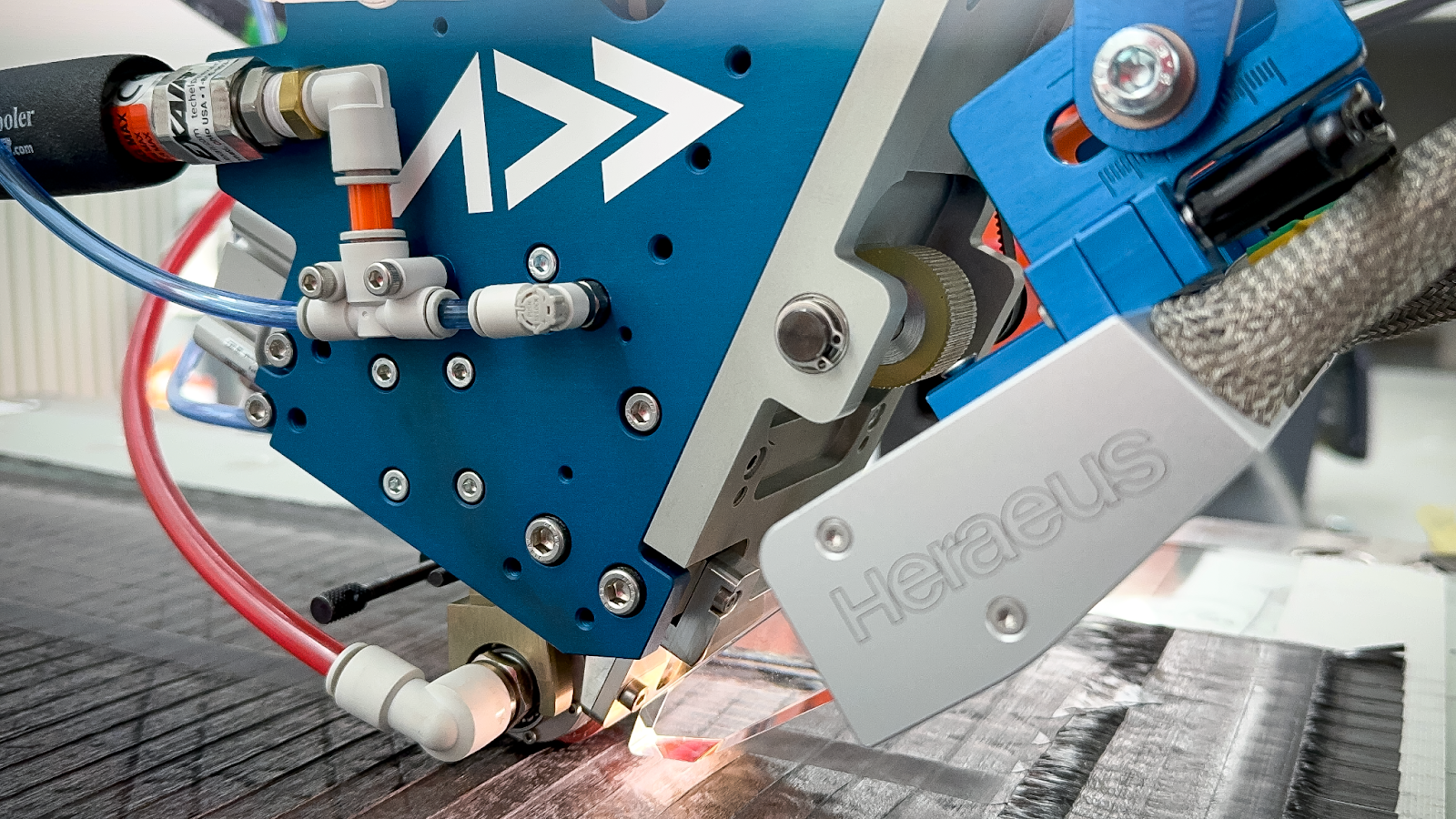
Automated Fiber Placement (AFP) systems like Addcomposites' AFP-XS can enable precise, repeatable layup of structural battery prepreg with controlled fiber orientation and electrolyte distribution - critical for achieving consistent multifunctional performance.
Manufacturing Process Overview
Manufacturing structural battery composites requires integrating composite manufacturing with battery assembly—two processes with very different requirements and sensitivities.
Material Preparation
Carbon Fiber Surface Treatment: Desizing via solvent extraction (acetone, MEK) or thermal treatment (400-500°C in inert atmosphere). This removes epoxy sizing that blocks lithium intercalation. Necessary for anode fibers; less critical for cathode substrate. Must balance electrochemical access vs mechanical interface.
Surface Oxidation (Optional): Electrochemical treatment in acidic or basic solutions. Controlled introduction of oxygen functional groups. Improves fiber-electrolyte adhesion. Moderate penalty to electrochemical performance.
Quality Control: Surface oxygen content measurement (XPS, FTIR), water contact angle measurement, and tensile testing of treated fibers (ensure no mechanical damage).
Electrolyte Precursor Mixing
For RIPS Systems: Mix PEO (molecular weight 100k-600k) with lithium salt (LiTFSI typical). Dissolve in solvent (acetonitrile common). Add epoxy resin and hardener. Controlled mixing to achieve homogeneous precursor. Degas under vacuum. Store at low temperature (-20°C typical) until use.
Critical Parameters: PEO:epoxy ratio (determines final properties), salt concentration (affects conductivity and phase separation), mixing temperature and time, degassing thoroughness.
For Prepreg Systems: Prepare similar precursor but at elevated temperature. Impregnate carbon fiber fabric via heated rollers or solution bath. Partial cure/B-stage to tackiness. Store refrigerated in inert atmosphere. Shelf life is limited: 1-3 months typical [4, 10].
Cathode Coating Application
Electrophoretic Deposition (EPD) — Most successful method [36]:
Prepare suspension of LiFePO₄ particles + conductive carbon + binder in solvent. Carbon fiber fabric as working electrode in EPD bath. Apply DC voltage (50-200V typical). Charged particles migrate and deposit on fiber. Rinse, dry, and optional thermal treatment to improve adhesion.
Advantages: Uniform coating even deep in fiber bundles. Controlled loading via time, voltage, concentration. Scalable process.
Challenges: Ensuring coating adhesion through subsequent processing. Maintaining uniform coating across large areas. Avoiding excessive coating thickness (mechanical stiffness).
Laminate Lay-Up and Assembly
Typical structure for single-cell laminate:
Structural Battery Cell Stack
Single-cell laminate lay-up sequence — from positive current collector through the electrode/separator stack to negative current collector
Critical Considerations: Electrical Isolation (separator must completely prevent anode-cathode contact, glass fiber fabric most common), Current Collection (metal foils integrated into layup, tabs brought out for external connection), and Fiber Orientation (can orient plies for mechanical requirements: 0°, 90°, ±45° typical).
Consolidation and Cure
Processing Methods:
- Vacuum Bag/Autoclave: Most common for research-scale. Typical: 6 bar pressure, 120°C, 2-4 hours. Inert atmosphere possible (N₂ bag).
- Press Molding: Heated platens with controlled pressure. Faster cycle time. Good for flat panels.
- Vacuum-Assisted Resin Infusion: Dry fabric layup. Vacuum-driven electrolyte infiltration. Better fiber wet-out but more complex tooling.
Process Control: Temperature Profile is critical for RIPS systems where cure rate affects phase separation (too fast = heterogeneous morphology; too slow = complete phase separation). Pressure ensures fiber wet-out and consolidation. Atmosphere Control requires moisture exclusion (PEO is hygroscopic, Li salts moisture-sensitive) and dry N₂ or Ar atmosphere preferred.
Formation Cycling
Before structural use, batteries undergo electrochemical formation:
- Purpose: Form stable SEI on anode, condition cathode-electrolyte interface, identify defects (shorts, low capacity)
- Typical Protocol: Initial charge at C/20 to full capacity → Rest period (2-4 hours) → Discharge at C/20 → Repeat for 2-4 additional cycles → Capacity measurement and verification
- Formation Temperature: Typically performed at 60°C (elevated to aid SEI formation)
Manufacturing Challenges and Scalability
Paths to Manufacturability
- Automated Fiber Placement (AFP): Could enable automated layup of structural battery prepreg with precise control
- Roll-to-roll Processing: Continuous cathode coating and electrolyte impregnation
- In-line Quality Monitoring: Real-time sensors during processing to identify defects
- Standardized Cell Building Blocks: Develop modular structural battery "cells" that can be assembled into larger structures
Addcomposites' AFP technology offers the precision and repeatability needed to transition structural batteries from lab-scale to production, with real-time process monitoring and multi-robot scalability.
Several groups are actively working on these challenges [17, 28], but significant development remains before high-volume production is feasible.
Real Applications
Structural Battery Application Roadmap
Technology readiness and deployment timeline — from laboratory proof-of-concept through automotive entry to primary aerospace structures
Current Demonstrations
1. CubeSat Structural Power (Moyer et al. 2020 [18])
Application: Small satellite power-structure integration. Design: 1U CubeSat chassis panel (10cm × 10cm).
Significance: First flight-relevant demonstration showing that structural batteries can meet real performance requirements.
2. UAV Wing Demonstrator (Various Groups)
Application: Unmanned aerial vehicle wing spar/skin. Energy: 15-20 Wh/kg (wing structural mass basis). Flight time extension: 25-40% vs baseline. Sustained flight loads with fatigue testing ongoing.
3. Electric Vehicle Body Panel Prototypes
Application: Hood or trunk lid for EV. Sandwich structure with structural battery core. Capacity: 200-500 Wh per panel. Range extension: 10-25 km.
Application Suitability Matrix
| Application | Mass Value | Mech. Req. | Elec. Req. | Safety/Cert | Readiness |
|---|---|---|---|---|---|
| Small UAV | Very High | Moderate | Moderate | Moderate | 3-5 years |
| Satellite | Very High | Low-Mod | Low | High | 3-5 years |
| Laptop chassis | High | Low | Low-Mod | Moderate | 5-7 years |
| EV body panel | High | Moderate | Moderate | Very High | 7-10 years |
| Aircraft interior | Very High | Moderate | Moderate | Very High | 10-15 years |
| Aircraft primary | Very High | Very High | Moderate | Extreme | 15-20+ years |
Near-Term Viable Applications (3-5 years)
1. Small UAVs and Drones
Why promising: Mass is THE critical constraint. Moderate mechanical loads. Lower safety barrier (minimal human risk). Existing regulatory framework. High value of flight time extension.
Technical requirements achievable: 40-60 Wh/kg energy, 500 cycle life, moderate power (C/5 discharge acceptable), operate 50-70°C (manageable with thermal design).
2. Satellites (CubeSats, Small Sats)
Why promising: Extreme mass value ($10,000+/kg to orbit). Vacuum environment (no moisture concerns). Temperature control needed anyway. Moderate cycle requirements. Precedent for novel technologies in space.
3. Portable Electronics (Premium Segment)
Why promising: Space savings valued. Lower safety requirements than automotive. Moderate loads. Willing to pay premium for thin/light. Technical requirements: 50-80 Wh/kg, 300-500 cycles adequate (device lifetime ~2-3 years).
Medium-Term Applications (5-10 years)
1. Electric Vehicle Non-Critical Structures
Targeting hood, trunk, interior panels, load floors. Requires 60-80 Wh/kg, 1000 cycles, crash safety demonstration, fire propagation resistance, automotive cost targets (<$150/kWh ultimately).
2. Commercial Vehicles and Fleets
May adopt earlier than passenger vehicles due to fleet economics (TCO optimization), more controlled use cases, centralized maintenance, and willingness to accept higher initial cost for operational savings. Target applications: delivery van body panels, bus interior structures, truck sleeper cab panels.
Long-Term Applications (10-20+ years)
1. Aircraft Primary and Secondary Structure
The "holy grail" but faces enormous challenges. Requires: 100 Wh/kg, 5000 cycles (20-30 year service life), damage tolerance, fire safety, lightning strike protection, and long-term environmental durability. Could enable 20-30% range extension for electric aircraft and new aircraft designs impossible with conventional batteries.
2. Automotive Body-in-White
Primary load-bearing chassis integration. Requires crash safety certification, long-term durability (15+ years, 200k+ miles), 2000 cycles, 80-100 Wh/kg. If achievable, could enable 40-50% mass reduction in EV structure+battery system.
The Challenges
Despite significant progress, structural battery composites face major hurdles before widespread deployment:
1. Performance Gap
The Reality
Current: 25-35 Wh/kg @ 25-30 GPa. Target for most applications: 60-100 Wh/kg @ 40-60 GPa. Gap: 2-3× improvement needed in both metrics simultaneously.
Why It's Hard: The fundamental property conflicts (conductivity-stiffness trade-off, interface strength vs electrochemical access) have no obvious resolution path that reaches target performance.
Possible Paths Forward: Novel electrolyte chemistries (beyond PEO), higher-performing carbon fiber electrodes (graphitic CF, CNT forests), thinner separators enabling higher active material fraction. But each faces its own challenges.
2. Cycle Life and Durability
Current Status: 200-500 cycles typical to 80% capacity retention. Applications need 500-5000+ depending on use case.
Degradation Mechanisms: All the degradation modes stack: SEI growth (like conventional batteries) + Interfacial debonding (unique to structural batteries) + Mechanical fatigue (from structural loading) + Environmental aging (moisture, thermal cycling).
Critical Unknown: Long-term durability data doesn't exist. Most studies are <1 year duration. Applications require 5-20 year lifetime prediction.
3. Safety Considerations
Structural batteries create new safety scenarios:
- Mechanical Damage → Electrical Short: If structure is impacted (crash, tool drop, foreign object), separator compression or penetration leads to anode-cathode contact, internal short circuit, and potential thermal runaway.
- Fire Propagation: Structural battery may be distributed across large area. Fire in one section could propagate to others. Difficult to contain compared to centralized battery pack.
- Failure Consequences: Loss of structural integrity AND power simultaneously. Coupled failure mode: electrical failure may cause mechanical failure and vice versa.
4. Manufacturing and Scale
Lab-scale fabrication (<1 m² panels), manual processes, 30-50% yield typical, cost >$1000/kWh estimated (vs $100-150/kWh for automotive Li-ion).
Even with scale, structural batteries will likely cost more per kWh than conventional batteries due to more complex materials, more processing steps, lower material utilization, and higher quality requirements. However, system-level cost could be lower due to elimination of battery pack housing and TMS hardware, reduced structural mass, and simplified assembly.
5. Modeling and Simulation
No validated models exist for coupled electro-chemo-mechanical degradation. Interface evolution not well understood. SOC-dependent mechanical properties not characterized. Damage tolerance modeling essentially absent.
Needed: Multi-physics finite element models (mechanical + electrochemical + thermal), homogenization approaches for composite-level properties, interfacial cohesive zone models with electrochemical coupling, machine learning to accelerate design space exploration [15].
6. Standardization and Testing
No standards exist for structural batteries. Each research group uses different material systems, different performance metrics, and different test protocols—making comparison and benchmarking difficult.
7. Fundamental Scientific Questions
Despite 15+ years of research, fundamental questions remain about interface chemistry (what determines SEI composition in PEO-based electrolytes?), charge transport (what limits Li⁺ transport in bicontinuous electrolytes?), degradation mechanisms (what are the dominant failure modes limiting cycle life?), and carbon fiber electrochemistry (can we develop carbon fiber with graphitic domains for higher capacity?). Answering these requires fundamental research using advanced characterization (in-situ TEM, synchrotron X-ray, neutron scattering, operando spectroscopy).
Future Directions
Where is the field headed? Several promising research directions:
1. Advanced Electrolyte Systems
Beyond PEO: Polyethylene oxide has dominated structural battery electrolytes, but alternatives are emerging:
- Polycarbon Bicarbonate (PBC) Electrolytes: Higher mechanical modulus than PEO (3-5 GPa), comparable ionic conductivity at elevated temperature, better adhesion to carbon fiber. Still in early research phase [23].
- Composite Solid Electrolytes: Inorganic fillers (ceramic Li-conductors) in polymer matrix. Potential for high conductivity + stiffness. Examples: LLZO nanoparticles in PEO.
- Ionic Liquid Polymer Gels: Room-temperature operation possible. High conductivity (10⁻⁴ to 10⁻³ S/cm @ 25°C). Mechanical properties remain challenge [11].
- Single-Ion Conductors: Anion tethered to polymer backbone. Only Li⁺ mobile → higher transference number. Could improve power performance.
2. Novel Electrode Materials
- Graphitic Carbon Fiber: Develop CF with higher graphitic character for better lithiation. Mesophase pitch-based CF (more graphitic than PAN-based). Could achieve capacity 200-300 mAh/g (2-3× current).
- CNT Forest Electrodes: Vertically aligned carbon nanotube forests. Very high surface area, excellent electrical conductivity, can achieve high capacity (200-300 mAh/g) [22].
- Silicon-Enhanced Anodes: Incorporate Si nanoparticles on CF surface. Si capacity: 3579 mAh/g (theoretical). Challenge: Si volume expansion (300%).
- Alternative Cathode Materials: LiNi₀.₈Mn₀.₁Co₀.₁O₂ (NMC811) at 4.2V for higher energy density, LiMn₂O₄ for lower cost, and Sulfur Cathodes for very high theoretical capacity.
3. Multiscale Design and Optimization
Computational Design: Machine Learning Material Discovery to predict properties of novel electrolyte compositions [15]. Topology Optimization for material distribution within structure [25]. Multi-Objective Optimization for simultaneously optimizing conflicting objectives.
Hierarchical Design: Optimize at multiple length scales from nanoscale (electrolyte phase morphology) through microscale (fiber-matrix interface), mesoscale (laminate stacking sequence), to macroscale (structural battery placement in vehicle/aircraft).
4. Smart Structural Batteries
Integrate sensing and diagnostics:
- Embedded Sensors: Fiber optic sensors for strain and temperature distribution. Acoustic emission sensors for damage detection. Impedance sensing for SOC and SOH.
- Digital Twin: Combine sensor data with physics-based models. Real-time estimation of remaining useful life. Predictive maintenance scheduling.
- Self-Healing Materials: Incorporate healing agents in electrolyte matrix. Automatic repair of microcracks. Could extend cycle life significantly. Early research stage.
5. Manufacturing Innovation
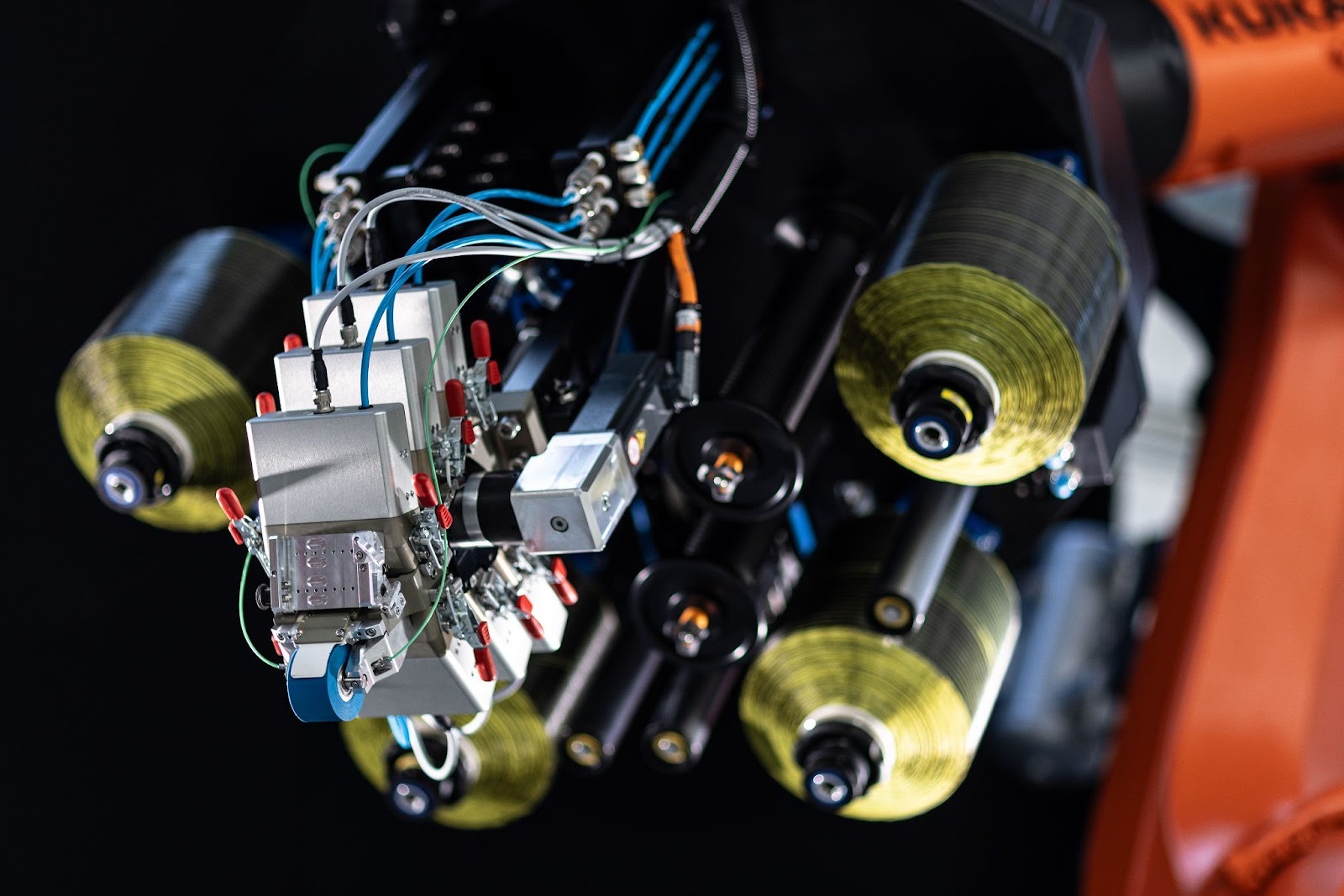
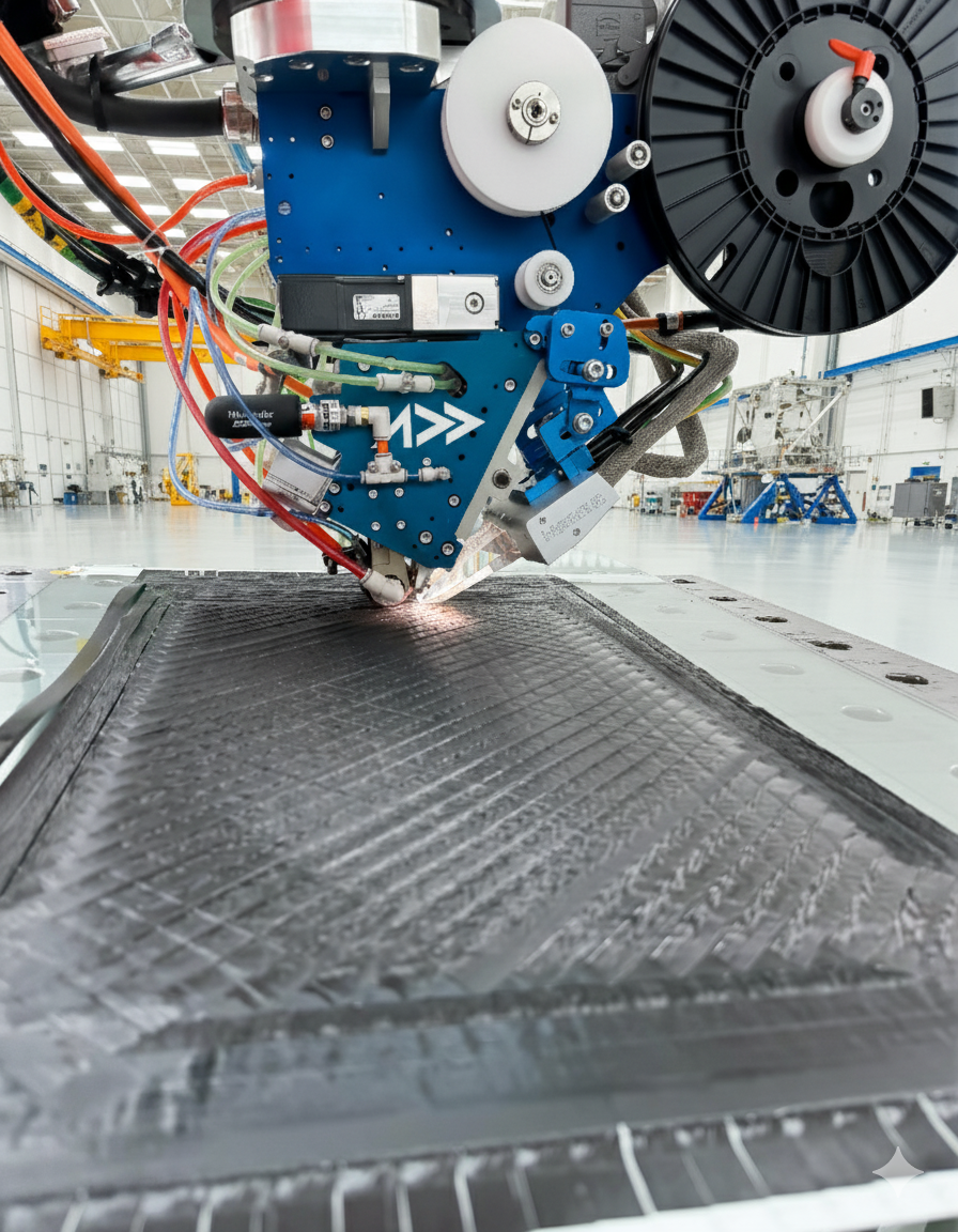
Automated Fiber Placement (AFP) for Structural Batteries
Advanced AFP systems with integrated sensing (like AddComposites' smart AFP solutions) can monitor placement quality in real-time, essential for detecting defects in structural battery manufacturing where electrical and mechanical performance are coupled.
AFP could enable: Precise layup of structural battery prepreg, variable electrolyte thickness for performance optimization, in-situ monitoring during placement, and higher reproducibility vs hand layup.
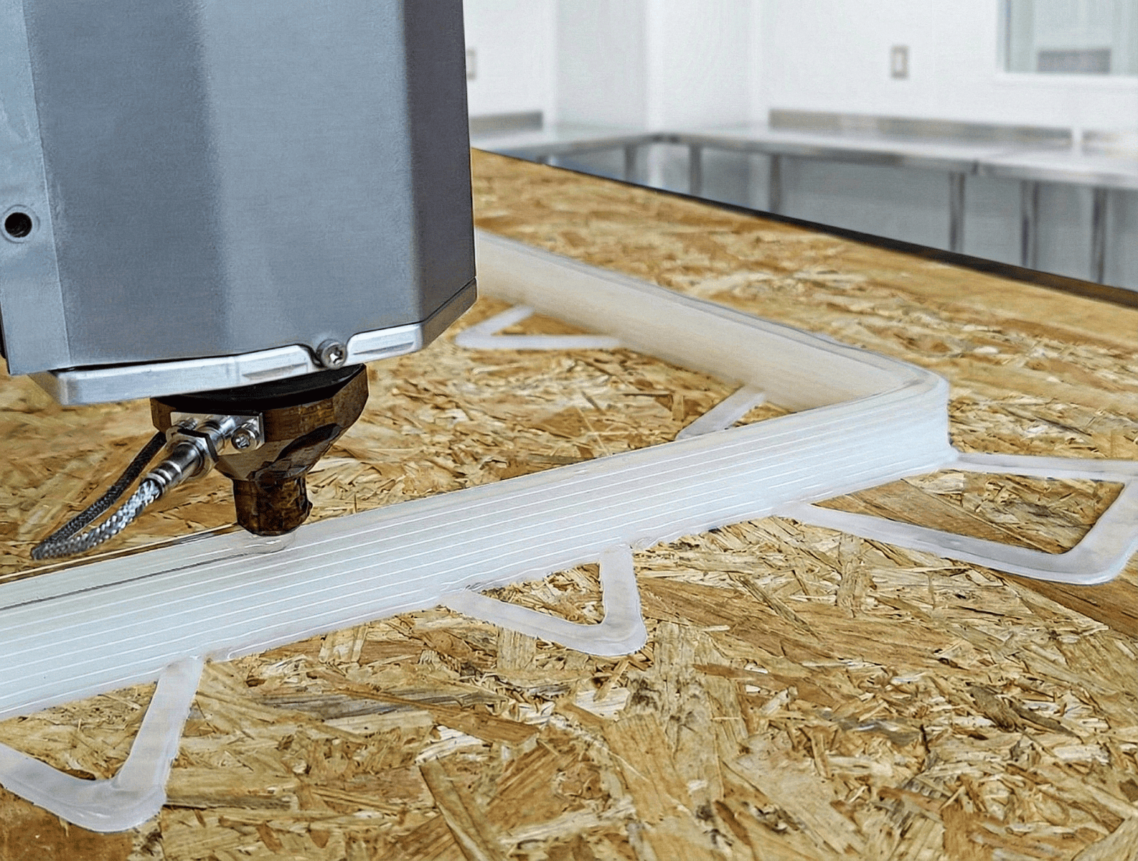
Additive Manufacturing Integration
Addcomposites' ADDX system printing complex 3D geometries that could enable structural battery designs with optimized electrode placement and electrolyte distribution - architectures impossible with conventional flat laminate manufacturing.
3D printing of structural battery components: print cathode structures with controlled architecture, print electrolyte with graded composition, print complete structural battery geometries. Could enable complex geometries impossible with traditional methods.
Continuous Processing: Roll-to-roll manufacturing enables continuous cathode coating on fiber, continuous electrolyte impregnation, in-line curing, and much higher throughput with lower cost.
6. Alternative Chemistries
Structural Supercapacitors [5, 39]
Advantages: Much higher power density. Longer cycle life (>100,000 cycles). Simpler chemistry. Wider operating temperature.
Applications: Regenerative braking energy capture. High-power bursts (acceleration, take-off). Complement to structural batteries.
Structural Zinc Batteries
Advantages: Safer (non-flammable aqueous electrolyte). Lower cost materials. Reasonable energy density (100-200 Wh/kg possible).
Status: Early research, little data on structural integration.
7. Application-Driven Development
Rather than one-size-fits-all, develop optimized structural batteries for each application:
- For UAVs: Prioritize energy density over cycle life (500 cycles sufficient). Moderate mechanical requirements. Optimize for 50-70°C operation.
- For EVs: Prioritize cycle life (>2000 cycles) and safety. High mechanical robustness. Room temperature operation essential. Cost target <$200/kWh.
- For Aerospace: Extreme reliability and safety. Long life (>5000 cycles, 20+ years). Damage tolerance paramount. Cost less critical.
8. Collaborative Frameworks
Successful deployment requires collaboration: Academics (fundamental research, new materials), Industry (manufacturing, application knowledge, funding), Government (funding, regulatory frameworks).
Examples: EU Horizon projects (Clean Aviation, Clean Automotive), US DOE Vehicle Technologies Office programs, Industry consortia (automotive OEMs, aerospace). Open data and benchmarking — making data openly available, creating shared databases of material properties, and benchmarking standard test procedures will accelerate collective progress.
The Bottom Line
Here's what you need to know about structural battery composites:
The concept works
Multiple groups have demonstrated functional prototypes combining meaningful energy storage with structural performance.
Interfaces are everything
The electrolyte-matrix and electrode-electrolyte interfaces determine success or failure—this is where the field's hardest problems live.
Current performance
~35 Wh/kg at 25 GPa represents the state-of-the-art—about 10-15% of battery energy density while providing real structural function.
System-level benefits
When you account for mass savings, even modest intrinsic performance delivers significant vehicle/aircraft-level advantages.
The gap to close
Manufacturing scalability, long-term durability data, and certification pathways are the barriers between lab demonstrations and products.
Timeline
Expect UAV applications within 3-5 years, automotive within 5-10 years, aerospace primary structure in 10+ years.
The structural battery field has matured from an academic curiosity to a serious engineering endeavor. The fundamental science is increasingly understood, manufacturing approaches are being developed, and application pull from aerospace and automotive sectors is strong. Success will require continued progress in interface engineering—the topic at the heart of this review.
References
[1] Asp, L.E., Greenhalgh, E.S. (2014). Structural power composites. Composites Science and Technology, 101, 41-61.
[2] Asp, L.E., et al. (2019). A structural battery and its multifunctional performance. Advanced Energy and Sustainability Research, 2(3), 2000093.
[3] Snyder, J.F., Carter, R.H., Wetzel, E.D. (2007). Electrochemical and mechanical behavior in mechanically robust solid polymer electrolytes for use in multifunctional structural batteries. Chemistry of Materials, 19(15), 3793-3801.
[4] Carlson, T., et al. (2013). Structural carbon fibre composite/PEO-based solid polymer electrolyte multifunctional energy storage. Composites Science and Technology, 84, 16-22.
[5] Shirshova, N., et al. (2013). Structural composite supercapacitors. Composites Part A, 46, 96-107.
[6] Kjell, M.H., et al. (2011). PAN-based carbon fiber negative electrodes for structural lithium-ion batteries. Journal of the Electrochemical Society, 158(12), A1455.
[7] Chaudhary, R., et al. (2024). Unveiling the multifunctional carbon fiber structural battery composite. Advanced Energy Materials.
[8] Liu, Y., et al. (2023). Effect of electrode surface treatment on carbon fiber based structural supercapacitors. Composites Part B, 252, 110506.
[9] Tu, V., et al. (2020). Performance of bicontinuous structural electrolytes. Electrochimica Acta, 357, 136855.
[10] Ihrner, N., et al. (2017). Structural lithium ion battery electrolytes via reaction induced phase-separation. Journal of Materials Chemistry A, 5, 25652.
[11] Feng, Y., et al. (2022). Short carbon fiber reinforced epoxy-ionic liquid electrolyte composite for structural battery applications. Composites Part B, 232, 109617.
[12] Wang, A., et al. (2018). Review on modeling of the anode solid electrolyte interphase (SEI) for lithium-ion batteries. npj Computational Materials, 4, 15.
[13] Peled, E., Menkin, S. (2017). Review—SEI: Past, present and future. Journal of the Electrochemical Society, 164(7), A1703.
[14] Carlstedt, D., Asp, L.E. (2020). Performance analysis framework for structural battery composites in electric vehicles. Composites Part B, 186, 107822.
[15] Johannisson, W., et al. (2023). Computational micromechanics and machine learning-informed design of structural battery composites. Composite Structures.
[16] Johannisson, W., et al. (2018). Multifunctional performance of a carbon fiber UD lamina electrode for structural batteries. Composites Science and Technology, 168, 81-87.
[17] Asp, L.E., et al. (2021). Structural battery composites: A review. Functional Composites and Structures, 3, 093001.
[18] Moyer, K., et al. (2020). Carbon fiber reinforced structural lithium-ion battery composite: Multifunctional power integration for CubeSats. Energy Storage Materials, 24, 676-681.
[19] Reece, R., et al. (2020). Structural composite energy storage devices. Materials Today Energy, 15, 100374.
[20] Deka, B.K., et al. (2017). Multifunctional enhancement of woven carbon fiber/ZnO nanotube-based structural supercapacitor. Chemical Engineering Journal, 325, 672-680.
[21] Thomas, J.P., Qidwai, M.A. (2004). Mechanical design and performance of composite multifunctional materials. Acta Materialia, 52, 2155-2164.
[22] Senokos, E., et al. (2017). Macroscopic fibres of CNTs as electrodes for multifunctional electric double layer capacitors. Carbon, 123, 180-187.
[23] Xu, J., et al. (2022). PEO-based polymer blend electrolyte for composite structural battery. Journal of Power Sources, 522, 231009.
[24] Nguyen, S.N., et al. (2021). Structural power performance of laminated composites with integrated lithium-ion batteries. Composites Part B, 225, 109273.
[25] Patel, A., et al. (2023). Multiphysics topology optimization of a multifunctional structural battery. Structural and Multidisciplinary Optimization, 66, 46.
[26] Galos, J., et al. (2021). Energy storage structural composites with integrated lithium-ion batteries: A review. Advanced Materials Technologies, 6, 2001059.
[27] Meng, F., et al. (2023). Porous structural battery composite for coordinated integration of energy storage and load bearing. Composites Part A, 175, 107769.
[28] Asp, L.E., Greenhalgh, E.S., Nikopoulou, A., editors. (2023). Structural Battery Composites. Wiley.
[29] Hopkins, B.J., et al. (2020). In situ characterization of structural battery electrodes. ACS Applied Energy Materials, 3, 10138-10147.
[30] Navarro-Suárez, A.M., et al. (2020). Development of multifunctional structural batteries. Journal of Applied Polymer Science, 137, 49243.
[31] Schneider, L.M., et al. (2019). Bicontinuous electrolytes via thermally initiated polymerization for structural lithium ion batteries. ACS Applied Energy Materials, 2, 4362-4369.
[32] Ladpli, P., et al. (2019). Multifunctional energy storage composite structures with embedded lithium-ion batteries. Journal of Power Sources, 414, 517-529.
[33] Wetzel, E.D., et al. (2004). Structural capacitors for multifunctional power. Proceedings of SPIE, 5387, 1-9.
[34] Ekstedt, S., et al. (2010). Structural batteries made from fiber reinforced composites. Plastics, Rubber and Composites, 39, 148-150.
[35] Jacques, E., et al. (2013). Piezo-electrochemical energy harvesting with lithium-intercalating carbon fibers. ACS Applied Materials & Interfaces, 5, 5050-5057.
[36] Hagberg, J., et al. (2018). Lithium iron phosphate coated carbon fiber electrodes for structural lithium ion batteries. Composites Science and Technology, 162, 235-243.
[37] Park, M., et al. (2021). Ultra-thin, mechanically robust solid electrolyte for structural battery composites. Energy Storage Materials, 40, 223-230.
[38] Danzi, F., et al. (2020). Structural batteries: A review. Molecules, 25, 5454.
[39] Fredi, G., et al. (2022). Multifunctional structural supercapacitors based on carbon fibre and separator electrodes. Composites Science and Technology, 228, 109622.
[40] Lindbergh, G., et al. (2023). Structural battery materials and devices. Nature Reviews Materials.
Learn More
Have questions about structural battery composites or implementing advanced composite manufacturing?
Contact Us for a Consultation